LTspice® is a high performance SPICE simulation software.
You can download it at:
http://www.analog.com/en/design-center/design-tools-and-calculators/ltspice-simulator.html?gclid=EAIaIQobChMIypDD5NnE3AIV2JkbCh06Kw_CEAAYASAAEgLG2vD_BwE
Sunday, July 29, 2018
Resistor
A resistor is a passive two-terminal electrical component that implements electrical resistance as a circuit element.
The most common values are:
Resister values colour
The most common values are:
- 10Ω, 47Ω,100Ω, 220Ω, 330Ω, 470Ω, 680Ω
- 1kΩ, 2.2kΩ, 3.3kΩ, 4.7kΩ, 10kΩ,
- 22kΩ, 47kΩ, 100kΩ, 330kΩ, 1MΩ
Resister values colour
You can download a Resistor Values Calculator at:
http://code.msdn.microsoft.com/Resistor-Values-Calculator-cadb6af3
Types of Resistance;
Data and Specifications
https://youtu.be/jSPNvJ0XYCQ
Types of Resistance;
- Carbon Composition Resistor –Made of carbon dust or graphite paste, low wattage values
- Wire wound resistor
- Semiconductor Resistor –High frequency/precision surface mount thin film technology
- Carbon film resistor,
- Metal film resistor,
- Metal oxide film resistor,
- Metal glaze resistor.
- Foil resistor.
Data and Specifications
- Resistance values. ohm
- Power rating. Watts
- TCR (Temperature Co-efficient of Resistance). The rate at which the resistance of the material changes with increase in temperature, normally it is expressed in term of parts per million, per degree Celsius- (ppm/°C).
- Maximum temperature specification- °C
- Maximum Voltage specification - Volts.
- Tolerance.
Understanding Resistors and Temperature
A resistor's Temperature Coefficient of Resistance (TCR) tells how much its value changes as its temperature changes. It is usually expressed in ppm/°C (parts per million per degree Centigrade) units. What does that really mean?
Let's use an example: 50 ohm 100 Series precision resistor has a (standard) TCR of 20ppm/°C. That means its resistance will not change more than 0.000020 ohms (20.1,000,000) per ohm per degree Centigrade temperature change (within the rated temperature range of -55 to +145°C, measured from 25°C room temperature.)
Assume our resistor is in a product that heats up from room temperature to 50°C. To find our 50W resistor's (maximum) change caused by that 25°C rise, multiply 0.000020 times 50 (the resistor value) times 25 (the temperature change.) The resistor's value would change no more than 0.025 ohms. (0.000020 X 50 X 25 = 0.025W.).
Preferred values or E-series
As basis the E12 has been developed. E12 means that every decade (0.1-1, 1-10, 10-100 etc) is divided in 12 steps. The size of every step is equal to:
10^(1/12) = 1.21
One could also say every value is 21% or 1.21 times higher than the last, rounded to whole numbers. Because of this, all resistors with a tolerance of 10% overlap. The series looks as follows: 1– 1.2 – 1.5 – 1.8 – 2.2 – 2.7 – 3.3 – 3.9 – 4.7 – 5.6 – 6.8 – 8.2 – 10 etc. All these values can be powers of ten (1.2– 12 – 120 etc).
for more information, see:https://youtu.be/jSPNvJ0XYCQ
The most common series are:
- E6 20%
- E12 10%
- E24 5% (also available with 1%)
- E48 2%
- E96 1%
- E192 0.5% (also used for resistors with 0.25% and 0.1%).
The transistor as a switch
Ic = Vcc/Rl
Ib = Ic/hfe (min)
Rb = (Vcc - 0.7)/ Ib
Basic NPN Transistor Switching Circuit

Driving a LED (D1)
Wednesday, July 25, 2018
Welding electronic equipments
You can use a solderless breadboard to make test circuits, but if you want your circuit to last for more than a few days, you will want to solder the components together.
To solder the terminals of any electrical component on the tracks of a printed circuit board (PCB), a welder with a power of 15 - 25 watts is sufficient.
Solder Wire is an alloy composed of pure tin and lead, the percentage of which is indicated on the packaging always with two numbers, for example 60/40 - 50/50 - 33/67.The first number indicates the tin content. The second number indicates the lead content, in the electronic field, the 60/40 type is the most commonly used, this tin melts at a temperature of around 190 - 195 degrees.
The solder wire to be used in electronics is available in wire with two different diameters: the most common type has a diameter of 2 millimeters, the most professional one has a diameter of 1 millimeter.
Rather than applying solder to the soldering iron you should heat the part and then touch the solder to the heated part, letting it flow over the connection on which you’re working. After the connection is well coated you’ll remove the solder before removing the soldering iron. Let the connection cool completely.
You should always solder in well-ventilated workspaces. You never want to inhale solder smoke, especially if it’s lead solder as a result of its toxicity. It’s best to use protective equipment as well because molten solder can splatter; use goggles or safety glasses.

Saturday, July 21, 2018
Voltage regulators 78L05
Voltage regulators.
Voltage regulators provide a constant output voltage for a varied input voltage. In our case the 78L05 IC is an IC. positive voltage regulator that provide a +5V output voltage.
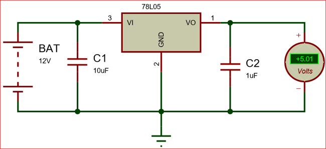
The circuit below a input max voltage of 12V is regulated to 5V using the 78L05.
78L05 Regulator Features:

Voltage regulators provide a constant output voltage for a varied input voltage. In our case the 78L05 IC is an IC. positive voltage regulator that provide a +5V output voltage.
The circuit below a input max voltage of 12V is regulated to 5V using the 78L05.
78L05 Regulator Features:
- 5V Positive Voltage Regulator
- Output Current upto 100mA
- Maximum Input Voltage is 30V
- Operating current(IQ) is 5mA
- Internal Thermal Overload and Short circuit current limiting protection is available.
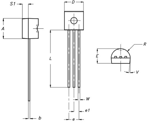
- Available in TO-92,SO-8 and SOT-89 package

Subscribe to:
Comments (Atom)


