Dielectric,
Dielectric is an electrical insulator that can be polarised by an applied electric field. When a dielectric is placed in an electric field, electric charges do not flow through the material as they do in an electrical conductor but only slightly shift from their average equilibrium positions causing dielectric polarization

he most common kinds of capacitors are:
- Ceramic capacitors have a ceramic dielectric.
- Film and paper capacitors are named for their dielectrics.
- Aluminum, tantalum and niobium electrolytic capacitors are named after the material used as the anode and the construction of the cathode (electrolyte)
- Polymer capacitors are aluminum, tantalum or niobium electrolytic capacitors with conductive polymer as electrolyte
- Supercapacitor is the family name for:
- Double-layer capacitors were named for the physical phenomenon of the Helmholtz double-layer
- Pseudocapacitors were named for their ability to store electric energy electro-chemically with reversible faradaic charge-transfer
- Hybrid capacitors combine double-layer and pseudocapacitors to increase power density
- Silver mica, glass, silicon, air-gap and vacuum capacitors are named for their dielectric.
- Electrolytic capacitor is a type of capacitor that uses an electrolyte to achieve a larger capacitance than other capacitor types. An electrolyte is a liquid or gel containing a high concentration of ions. Almost all electrolytic capacitors are polarized, which means that the voltage on the positive terminal must always be greater than the voltage on the negative terminal.
Read more http://www.capacitorguide.com/electrolytic-capacitor/
Capacitors types;
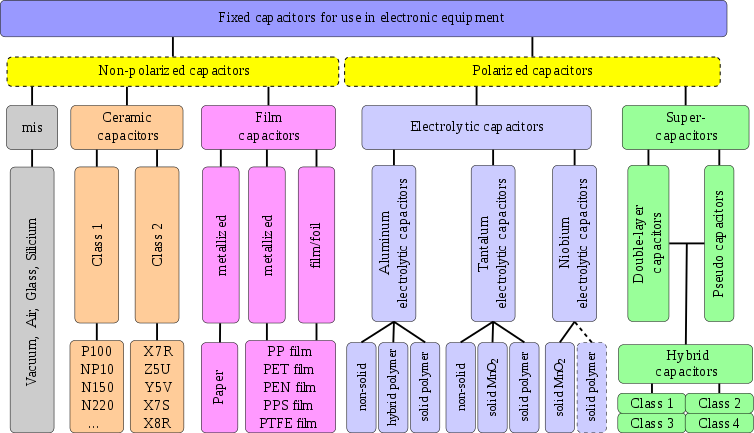
Table from: https://en.wikipedia.org/wiki/Capacitor_types.
Capacitance Units
| Prefix Name | Abbreviation | Weight | Equivalent Farads |
|---|---|---|---|
| Picofarad | pF | 10-12 | 0.000000000001 F |
| Nanofarad | nF | 10-9 | 0.000000001 F |
| Microfarad | µF | 10-6 | 0.000001 F |
| Milifarad | mF | 10-3 | 0.001 F |
| Kilofarad | kF | 103 | 1000 F |
Popular values:
100nF
6 pF
22pF
33 pF
0,1 uF
1 uF
10 uF
47 uF
100 uF